Today, the Morgan Silver Dollar Coin remembers the opening of the Niagara Cantilever Bridge on December 20, 1883.
Near Niagara Falls, the bridge provided for rail traffic between the U.S. and Canada.
From the Scientific American Supplement of March 28, 1885:
=====
The Niagara Cantilever Bridge.
At a meeting of the American Society of Civil Engineers in this city, a paper on the Cantilever Bridge at Niagara Falls, by C. C. Schneider. M. Am. Soc. C. E.. was lately read by the author.
The preliminary study and estimate for this double track railroad bridge was made at the request of the Central Bridge Company of Buffalo, by Mr. Schneider, in October, 1882, and he at that time concluded that the river span should be so designed as to allow it to be erected without false works, and that a hinged arch on the cantilever principle would be the proper form of construction, he having in the spring of 1882 designed the Fraser River Bridge for the Canadian Pacific Railway, where similar conditions existed precluding the use of false works.
After securing a profile of the site, the design and estimates were perfected, and a tender for the construction of the entire work submitted by the Central Bridge Company to the Niagara River Bridge Company, and after approval by their Consulting Engineer, Mr. Charles H. Fisher, M. Am. Soc. C. E., the contract was awarded on April 11, 1883, to the Central Bridge Company, on condition that the structure be completed on December 1 of the same year.
Mr. Schneider was appointed, by the Niagara River Bridge Co., Chief Engineer on April 26.
The work, both at the bridge site and the shops, was vigorously pushed, and the bridge was completed and opened for traffic on December 20, 1883, about eight months from the commencement of the work.
The bridge is over the Niagara River, about two miles below the Falls and 300 feet above the Railroad Suspension Bridge.
The bridge spans a chasm of 850 feet in width and 210 feet in depth to the surface of the water.
The river is 425 feet wide at the bridge site; the water has a velocity of 16.5 miles per hour at the center of the river. The depth is supposed to be from 50 to 80 feet.
The banks on both sides slope at about 45 degrees from the water’s edge to about 50 feet below the top of the cliff, above which they are horizontal.
The sloping banks consist of a mass of large boulders and broken stone from the hard limestone layer which forms the upper stratum, mixed with earth and debris.
This hard limestone, which has been undermined by the water acting upon it and cutting away the argillaceous rocks, has fallen in hard masses and formed a natural rip-rap, preventing further erosion.
The pits for the towers at the water’s edge were in this loose, hard stone. No solid rock was found.
It was determined to prepare the bed for the masonry upon the very large boulders at the bottom of the pits by filling to a depth of about 8 feet with beton Coignet, well rammed into all interstices on bottom and sides.
The foundation area for each pair of piers is about 1,000 square feet, and the weight about 5,930,000 pounds or 5,930 pounds per square foot.
The stability of this foundation was considered by two commissions of engineers, both of which commissions expressed themselves satisfied as to their stability.
The masonry of the piers is limestone laid in cement. They are 38 feet high above the beton.
The stones were lowered from the trestle, afterward used for erection of the towers and shore arms of the cantilevers. The anchorage piers are on the top of the cliffs.
They are built on a platform of plate-girders. connected by anchor-bars to the shore ends of the cantilevers, thus utilizing the weight of the whole mass of masonry of the piers.
Each anchorage pier weighs about 2,000,000 pounds.
The towers are 132.5 feet from top of masonry to centre of lower chord of cantilevers.
Each tower consists of four main posts, with horizontal struts and diagonal tie-rods. Each post is formed of steel plates and angles.
The horizontal struts divide the towers into five sections of nearly equal height. The posts have a batter of 1 in 8 at right angles, and of 1 in 48 parallel to the axis of the bridge.
The distance between centers of posts at their base is 60 feet 7.25 inches at right angles, and 30 feet 5.25 inches parallel to the axis of the bridge.
They rest on cast-iron shoes at the bottom. The tops consist of steel castings, which support the cantilever on 7.6 inch steel pins.
The structure carries a double track. It consists of two cantilevers resting on the towers, the shore ends being anchored to the anchorage piers, and the river ends connected by an intermediate span.
The distance between centers of anchorage piers is 910 feet 2.25 inches; length of each cantilever, 395 feet 2.31 inches ; length of intermediate span, 119 feet 9.88 inches.
The moving load assumed in proportioning the structure was a train on each track headed by two 66-ton locomotives, having 72,000 pounds on three pairs of drivers, spaced 6 feet between centers, followed by a train load of 2,000 pounds per lineal foot.
The floor system is proportioned for 78-ton consolidation engines. The lateral system is proportioned to resist a wind-pressure of 30 pounds per square foot on a train surface of 10 feet height, and upon the exposed surface of truss and floor system; the pressure on the train surface being considered a moving load. Strain sheets accompany the paper.
The tower posts, lower chords, center and end posts of cantilevers, pins, top-castings for towers, are of steel. All the other parts are of wrought iron, except the shoes for tower posts, filling rings, washers, and hand rail posts, which are of cast iron.
Each cantilever consists of a shore arm 195 feet 2.31 inches long, one panel 25 feet over the tower and a river arm of 175 feet length.
The cantilever trusses are divided by vertical posts into panels of 25 feet, with the exception of the end panel of the shore arm, which is 20 feet 2.31 inches; they have a double system of diagonals, and are spaced 28 feet between centers ; they are 56 feet deep over the towers, 26 feet over the last vertical post at the river end, and 21 feet over the last vertical post at the shore end.
The upper chords of the shore arm receive alternate tensile and compressive strains; loads which are applied between the anchorage and the tower produce compression, and those applied to the river arm or intermediate span produce tension.
These chords are of eye-bars, with a compression member of plates and angles, double latticed, packed between the bars.
The upper chord in tower panel and the upper chord of river arm are composed entirely of eye-bars. The lower chords and inclined end posts of the cantilevers are steel compression members of plates and angles.
The vertical posts over the tower supports are of steel, two plates and four angles. The intermediate vertical posts are of two channels double laced.
All the principal connections are made by steel pins 5.63 inches, 6.75 inches, and 7.5 inches diameter.
The cantilevers are connected to the anchorage piers by rockers permitting horizontal movement.
The intermediate span has five panels of 24 feet.
The heads of the eye-bars were formed by die forging.
The towers were erected by means of derricks on the false works, the material being lowered from the cliffs to the floor of the false works and thence to the towers.
The tower on the American side was begun August 29 and finished September 8; that on the British side was begun September 10 and finished September 18.
The shore arms of the cantilevers were then erected on the false works, a track laid on them, and the travelers for the construction of the river arms put in position.
These were substantial wooden frame works on iron wheels. The travelers were fastened by clamps to the floor-beams of the completed portion.
Each traveler had two derricks connected with a hoisting engine, by means of which the materials were lifted from cars and lowered to their place in the structure.
A hanging platform was suspended from the traveler.
The American shore arm was begun September 25, completed October 15. The Canadian shore arm was begun October 8, completed October 22.
The American river arm was begun October 28; the Canadian river arm was begun November 4.
The last connection was made November 22. The first track was completed December 6, on which day a locomotive crossed the bridge. The whole structure was completed December 19.
The bridge was formally opened and tested in the presence of a large number of engineers on December 20, 1883.
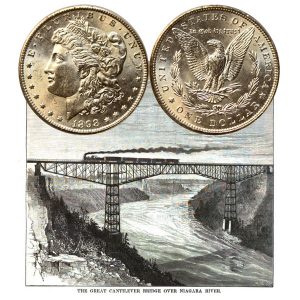
=====
The Morgan Silver Dollar Coin shows with an artist’s image of the Niagara Cantilever Bridge with a steam locomotive and cars on its tracks.